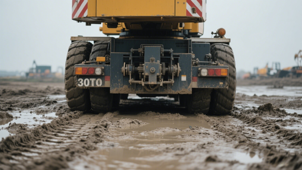
Mobile cranes in the 30-ton class are vital assets across construction, industrial, and infrastructure sectors. Their mobility enables rapid deployment, yet this agility hinges entirely on the stability provided by the ground beneath them. Understanding and managing terrain impact isn’t optional—it’s the bedrock of safe, efficient operations, especially when lifting near the crane’s rated capacity.
Table of contents
cnxjcm
Why Ground Conditions Dictate Success
A crane’s lifting capability is fundamentally constrained by its stability – and stability stems solely from adequate ground support. Poor conditions compromise this foundation, leading to:
- Reduced safe working load (even below chart values)
- Catastrophic risks (tipping, structural failure, load drops)
- Operational delays from remedial ground prep or aborted lifts
Terrain Risks & Operational Impacts
| Ground Condition | Primary Risks | Operational Impact |
|---|---|---|
| Soft/Unstable | • Outrigger sinkage • Ground subsidence • Tipping | • Mandates mats/cribbing • Significant capacity reduction • Extended setup time • Risk of immobilization |
| Uneven/Sloped (>1°) | • Shifted center of gravity • Uneven outrigger loading • Tipping | • Requires slope-specific derated charts • Critical boom positioning (uphill) • Avoid downhill/side lifts |
| Hard Surfaces | • Surface cracking/spalling • Hidden subsurface voids (e.g., utility trenches) | • Subsurface integrity verification needed • Mats essential for load distribution • Debris clearance critical |
| Obstructed Sites | • Crane/structure collisions • Utility strikes • Power line electrocution | • Demands 360° site survey • Spotter-assisted maneuvering • Minimum 10m power line clearance |
Ground Preparation: The Non-Negotiable Protocol
1. Comprehensive Site Inspection
- Survey for: erosion, water saturation, buried utilities, overhead obstructions, and subsurface anomalies (e.g., backfilled excavations).
- Document conditions with photos/notes for lift planning.
2. Ground Bearing Capacity Verification
- Critical lifts (>75% capacity): Conduct plate load tests or consult geotechnical reports.
- Routine lifts: Probe soil with steel rod; inspect existing equipment footprints for sinkage.
3. Stabilization Systems Deployment
- Mats: Use engineered timber/steel mats sized to distribute load (min. 2x outrigger pad area).
- Cribbing: Build level timber towers on slopes (>3°) to achieve horizontal outrigger setup.
4. Outrigger Best Practice
- Fully extend all outriggers onto prepared surfaces.
- Verify contact pressure: Use calibrated level gauges; zero float before lifting.
- Never compromise: Partial extension voids manufacturer’s load chart validity.
Stability Mechanics: How Ground Failure Occurs
1. Bearing Capacity Failure
- Soil shear stress > bearing capacity → Outrigger sinks → Crane tilts → Moment overload → Tip-over.
2. Slope-Induced Instability
- Gravity shifts crane CG downhill → Lifting force amplifies imbalance → Reduced tip-over resistance.
Load Chart Limitation: Charts assume ISO-standard conditions (level, compacted gravel @ 15 tons/m²). Any deviation requires strict adherence to manufacturer’s derating guidelines.
Consequences of Neglecting Ground Prep
Ignoring terrain risks cascading failures:
- Immediate Hazards: Crane tip-over, structural collapse, or falling loads → Personnel injury/fatality.
- Project Impacts: Work stoppage, equipment repair/replacement costs, regulatory penalties.
- Reputational Damage: Loss of client trust, litigation, insurance premium hikes.
These are preventable incidents – not accidents.
Terrain-Specific Best Practices
| Condition | Critical Actions |
|---|---|
| Soft Ground | • Deploy oversized mats (min. 2m² per outrigger) • Restrict lifts to ≤50% chart capacity • Monitor outrigger sinkage with laser levels • Keep recovery equipment (winch/mats) on standby |
| Slopes | • Verify slope angle with inclinometer • Boom uphill always + use derated charts • Achieve level setup via timber cribbing • Never lift with boom downhill/sideways |
| Hard Surfaces | • Place UHMW plastic/mats under outriggers • Scan for voids with ground-penetrating radar • Edge-protect mats from steel outrigger pads |
| Congested Sites | • 3D lift path simulation pre-operation • Dedicated spotters for blind zones • Live voltage detection near power lines • Dynamic repositioning via remote steering |
Built for Real-World Terrain
The 30 Ton Mobile Crane is purpose-built to handle real-world ground conditions. With a full-extension outrigger system, advanced hydraulic control, and a rugged telescopic boom, it’s designed for stable lifting even on challenging job sites.
Whether you’re working on soft soil, sloped surfaces, or constrained urban lots, this mobile crane provides the flexibility, safety features, and reliability required for efficient setup and confident operation. Its integrated load moment indicator and optional remote control system further enhance safety during complex terrain maneuvers.
Conclusion: The Ground Truth of Crane Safety
Every 30-ton lift lives or dies by its ground foundation. Success demands: quantified soil assessment, engineered load distribution systems, and strict adherence to terrain-derated protocols. Compromise here invites catastrophic instability.
This ground-first ethic safeguards lives through preventive stability, protects assets from structural failure, and ensures project continuity. Remember—the soil bearing your crane’s load simultaneously bears your professional legacy. Respect is non-negotiable.


