On a 100-ton rough terrain crane, boom design is the single biggest factor separating rated capacity from real lifting performance. Section count, profile geometry (oval, hexagonal, or U-shaped), pinning vs. fully powered telescoping, and the luffing cylinder geometry together determine how much weight the crane actually picks at a given radius — often differing by 15–25% between two machines with identical “100t” nameplates.
If you’re spec’ing or buying an RT crane for heavy infrastructure work, understanding what’s happening inside that boom matters far more than the tonnage stamped on the side.
Why the Boom Defines a 100-Ton RT Crane’s True Capability
Here’s a fact that surprises many first-time buyers: a 100-ton rough terrain crane almost never lifts 100 tons in practice. That figure is the maximum rated load at minimum radius — typically 3 meters — over the rear with full outriggers. Push the load out to 12 meters of radius, and you may be down to 25–30 tons. At 30 meters, perhaps 6–8 tons.
That curve isn’t fixed by the engine, the counterweight, or even the chassis. It’s dictated by the boom. The boom’s stiffness, weight, geometry, and how its sections nest together determine the load chart at every radius and every angle. Two cranes can share the same engine and counterweight, but if one uses a 5-section oval-profile boom and the other a 4-section U-profile boom, the load charts will read like two different machines.
This is why experienced fleet managers ask for the load chart before they ask the price. The boom is the load chart.
Section Count: More Isn’t Always Better
A 100-ton RT crane typically uses a 4-, 5-, or 6-section telescopic boom. Each added section gives you more reach — but at a cost.
The trade-off in plain terms
- Fewer sections (4): Stiffer, heavier per meter, less deflection, higher capacity at short to mid radius. Best for pure heavy lifting.
- More sections (6): Longer reach, lighter per meter when retracted, but more flex and lower capacity at long radius due to compounding deflection.
For instance, a 100-ton RT crane working a refinery turnaround — short radius, heavy vessels, frequent picks — benefits from a 4-section boom. A 100-ton RT working wind farm pre-assembly or tall tower work needs a 5- or 6-section boom to reach over obstructions.
The mistake we see most often? Buyers spec’ing the longest boom available “just in case,” then complaining the crane underperforms on heavy lifts. Each extra section adds 2–4 tons of boom weight, which eats directly into your capacity chart.
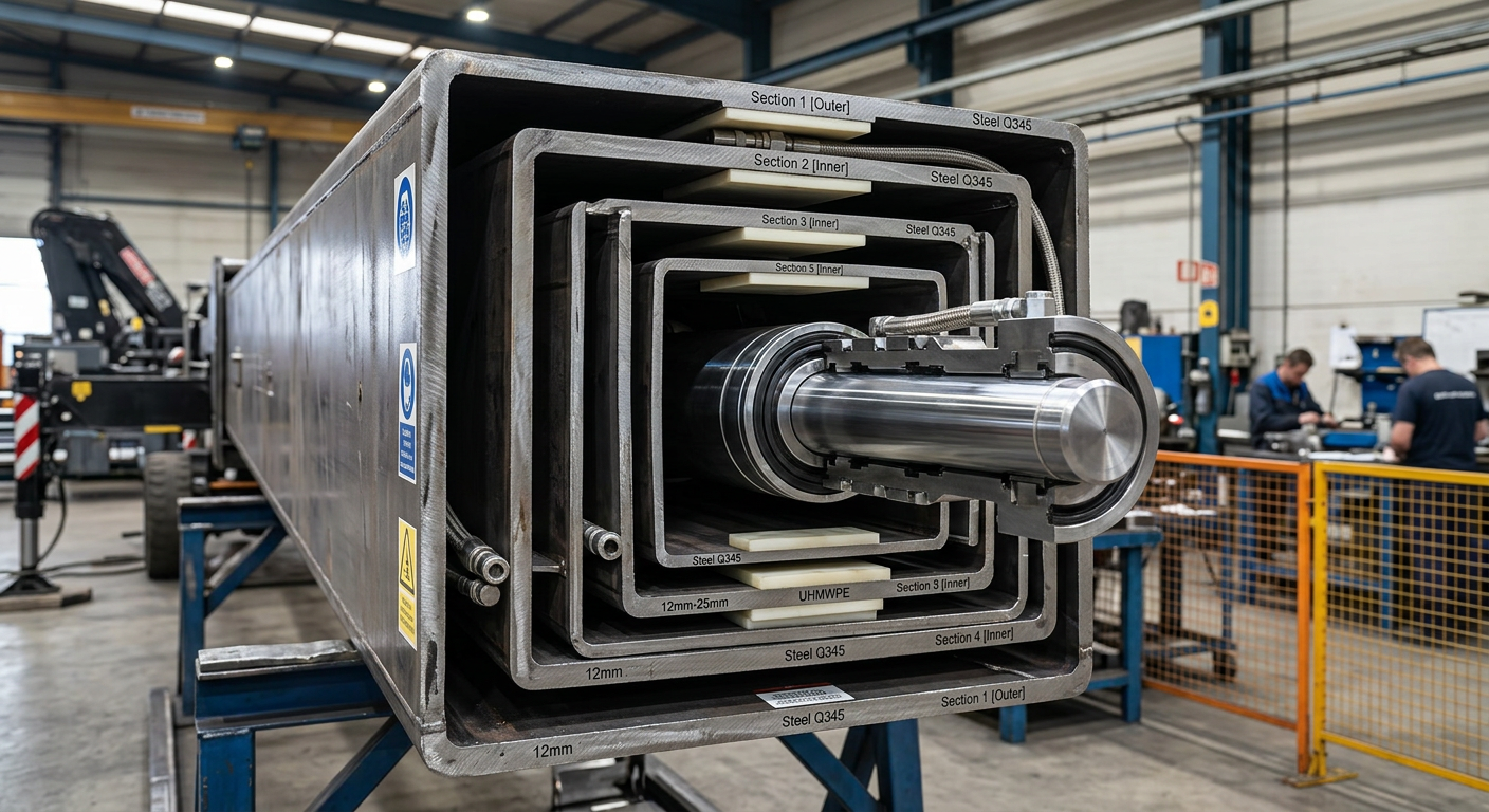
Boom Profile Geometry: Oval vs. U-Shape vs. Hexagonal
Look at the cross-section of a telescopic boom and you’ll see one of three profiles. The choice changes everything about how the boom behaves under load.
Oval (rounded) profile
Best torsional strength. Resists side-load and twisting when the load swings off-center. Common in European-design cranes. Heavier per meter but more forgiving when ground conditions cause minor crane tilt.
U-shape (with stiffeners)
Lighter, easier to manufacture, very strong in vertical bending. The current industry favorite for 80–160 ton RT cranes. Modern U-booms with internal sliding pads and welded longitudinal stiffeners now rival oval booms for lateral stiffness while shaving 8–12% of weight.
Hexagonal/octagonal
A compromise — good in bending and torsion, easier to fit telescoping cylinders inside. Found in some Japanese and Chinese designs. Slightly more complex to fabricate and align.
At cnxjcm we’ve moved most of our 100-ton class production to high-strength U-profile booms made from Q960 steel, which give us the weight savings of a U-shape with the rigidity normally associated with oval sections. You can read more about how this approach scales down on our 70 ton RT crane and up through the heavier classes.
Telescoping Systems: Pinned vs. Fully Powered
Open a boom up and you’ll find one of two mechanisms — and this is where load charts diverge the most.
Pinned (single-cylinder) telescoping
One hydraulic cylinder extends one section at a time, with each section locked by pins. The cylinder retracts, moves to the next section, pins it, and extends again. The result: a lighter boom because you don’t need cables, pulleys, or multiple cylinders running its full length.
The payoff is dramatic — a pinned 100-ton boom can be 1.5–2.5 tons lighter than the equivalent rope-and-cylinder design. That weight saving translates directly into higher capacity at every radius.
Synchronous (cable + cylinder) telescoping
All sections extend together via a cylinder driving cables and pulleys. Faster full-extension time and simpler logic for operators. But heavier, and the cable system needs periodic inspection and tensioning.
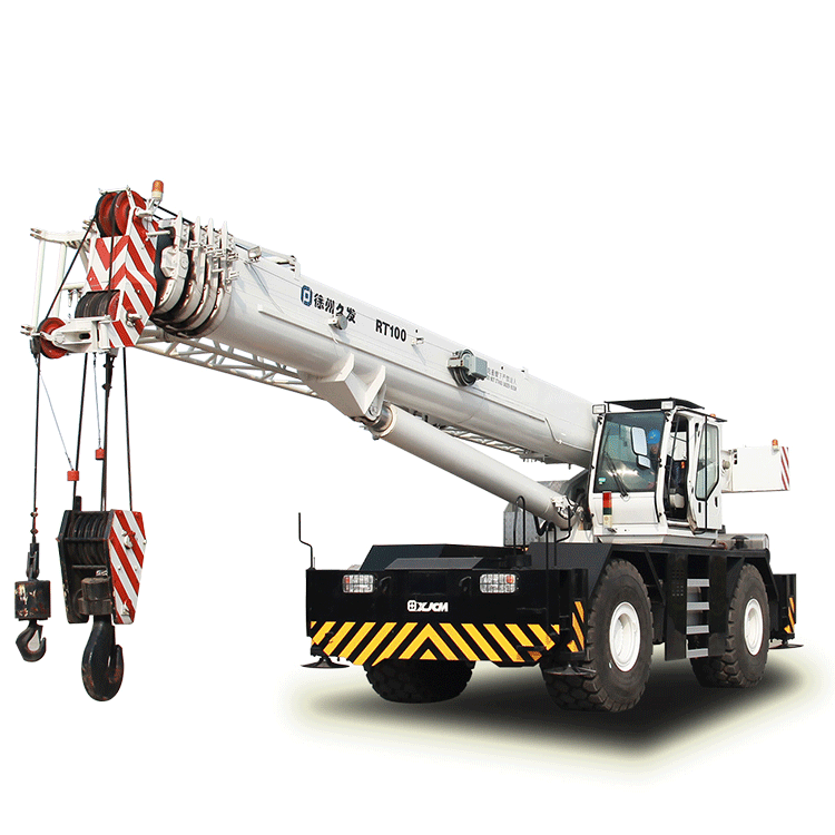
For a contractor doing many short picks per shift, synchronous is faster. For a heavy-lift specialist who positions the boom once and lifts, pinned is the better engineering choice. Most modern 100-ton RT cranes — including cnxjcm’s RT100 — use pinned single-cylinder telescoping for exactly this reason.
Luffing Geometry and Cylinder Placement
The luffing cylinder — the big ram that raises and lowers the boom — looks simple from outside. Its geometry, however, controls how much of the engine’s hydraulic power actually becomes lifting force.
Two design variables matter:
- Cylinder attachment point: A cylinder mounted further forward on the boom gives better leverage at low angles, where most heavy lifting happens. Mount it too far back and you lose capacity at the radii where you need it most.
- Single vs. dual cylinders: Most 100-ton RTs use a single large luffing cylinder. Some heavier configurations use twin cylinders for redundancy and reduced side-load. Twin systems are slightly heavier but offer smoother control under uneven load.
A real-world example: a Middle Eastern oilfield contractor we worked with was lifting wellhead equipment at 4–6 meter radius, mostly between 0 and 25 degrees boom angle. Switching from an older crane with a rear-mounted luffing cylinder to one with forward-mounted geometry gained them 9 tons of usable capacity at the same radius — without changing tonnage class.
Boom Material and Welding: Why Steel Grade Changes the Chart
Boom steel is not generic structural steel. Modern 100-ton class booms use high-strength low-alloy steels — typically Q690, Q890, or Q960 in Chinese grades, equivalent to S690QL through S960QL in European norms. The number is the yield strength in MPa.
Why does this matter to a buyer? Because doubling the yield strength of the steel lets engineers reduce wall thickness, which reduces boom weight, which raises capacity at every radius. A 100-ton boom built from Q690 might weigh 9 tons. The same geometric boom in Q960 weighs around 6.5 tons — and that 2.5-ton difference shows up as roughly 2 extra tons of usable load capacity at mid radius.
But high-strength steel demands precision welding. Pre-heating, controlled cooling, post-weld stress relief, and ultrasonic inspection of every longitudinal seam are non-negotiable. Cutting corners here is how booms develop fatigue cracks after a few thousand cycles. When you’re evaluating crane manufacturers, ask specifically about their boom welding qualification standards (AWS D14.3, EN 15085, or ISO 3834-2) and whether they do 100% non-destructive testing.
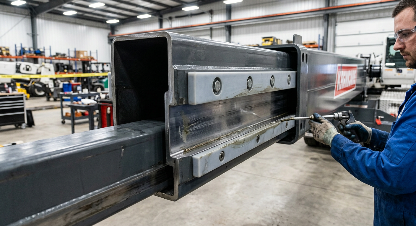
Sliding Pads, Wear Strips, and Why They Quietly Kill Performance
Inside the boom, between each pair of nested sections, sit synthetic sliding pads — usually a polymer composite like MC nylon or proprietary blends. They look unimportant. They are not.
Worn or undersized sliding pads cause two problems that show up as “loss of capacity” even though the load chart hasn’t changed:
- Boom deflection increases because sections rattle slightly in their carriers. The operator feels it as a soft, bouncy boom at long extension.
- Side-load resistance drops because the pads are what transfer lateral force between sections.
For a fleet operator running a 100-ton RT crane 2,000+ hours per year, sliding pad inspection should be part of every 1,000-hour service. Replacement is cheap. The downstream cost of ignoring them — premature boom wear, scoring inside the section walls, even cracked welds — is not.
Comparing Boom Configurations: What to Spec for Your Site
Choosing the right boom configuration starts with one question — what radius do you lift at most often? Once you know that, the rest falls into place.
Use the comparison table above as a starting point. For most general construction contractors, a 5-section U-profile boom with pinned telescoping hits the sweet spot: enough reach for steel erection and concrete placement, enough capacity for occasional heavy lifts. For specialized heavy-lift fleets — port maintenance, refinery work, transformer installation — a 4-section boom maximizes the load chart where you actually work.
For comparison with smaller machines, our 50 ton rough terrain crane typically uses a 4-section design, while the 25 ton rough terrain crane often uses 3 sections — the same principles apply down the tonnage scale.
One more practical note: don’t forget the jib. A 100-ton RT can carry an 8–17 meter swing-away jib that extends reach by 50%+. But every meter of jib reduces tip capacity. Spec the jib for the lightest, longest reach picks you’ll actually do — not aspirational ones.
Field Reality: Why Ground and Outriggers Multiply (or Cancel) Boom Performance
Here’s the part where engineering theory meets jobsite mud. The most beautifully designed boom in the world delivers zero rated capacity if the outriggers are sitting on soft fill, sloped ground, or unconsolidated soil.
A 100-ton RT crane at maximum capacity transmits 50–70 tons of force through each outrigger pad. If the soil bearing capacity is below that, the pad sinks, the chassis tilts, and the load chart is no longer valid. We’ve covered this in detail in our guide on ground conditions for safe mobile crane operations — the principles scale directly to the 100-ton class but with proportionally larger consequences.
For contractors working unprepared sites, the rough terrain category exists precisely for this reason. Big tires, high ground clearance, four-wheel drive, and outriggers sized for soft conditions. Combined with a well-designed boom, that’s what makes the rough terrain crane the go-to lifter for infrastructure work outside paved areas.
Putting It All Together: Specifying Your Next 100-Ton RT
If you’re sourcing a 100-ton rough terrain crane in 2026, here’s the short checklist that filters out 80% of mismatched purchases:
- Pull the full load chart — every radius, every boom length, every outrigger position. Compare apples to apples, not nameplates.
- Confirm boom section count matches your typical work radius and reach needs.
- Ask about boom steel grade (Q690 or higher) and welding certification.
- Verify telescoping system type — pinned single-cylinder is the modern standard for heavy lift duty.
- Check jib options and tip capacities at full extension.
- Confirm after-sales support including spare sliding pads, hydraulic seals, and field service coverage for your region.
At cnxjcm we’ve built rough terrain cranes for more than 40 export markets, with a 100-ton class engineered specifically for the heavy infrastructure and energy projects common across the Middle East, Africa, CIS countries, and Southeast Asia. If you’d like a load chart comparison or a configuration recommendation for your specific application, talk to our engineering team — we’ll match the boom to the job, not the other way around.


