Get the outrigger setup wrong and it doesn’t matter how good your crane’s load chart looks on paper — you’re either derating capacity you didn’t need to lose, or you’re setting up a tip-over waiting to happen. The three things that decide this every single time are extension position (full, mid, or minimum), ground bearing support under each pad, and leveling within tolerance before the boom ever moves. Nail those three and the rest of the lift is just following the chart.
Why Extension Position Changes Your Capacity Chart Entirely
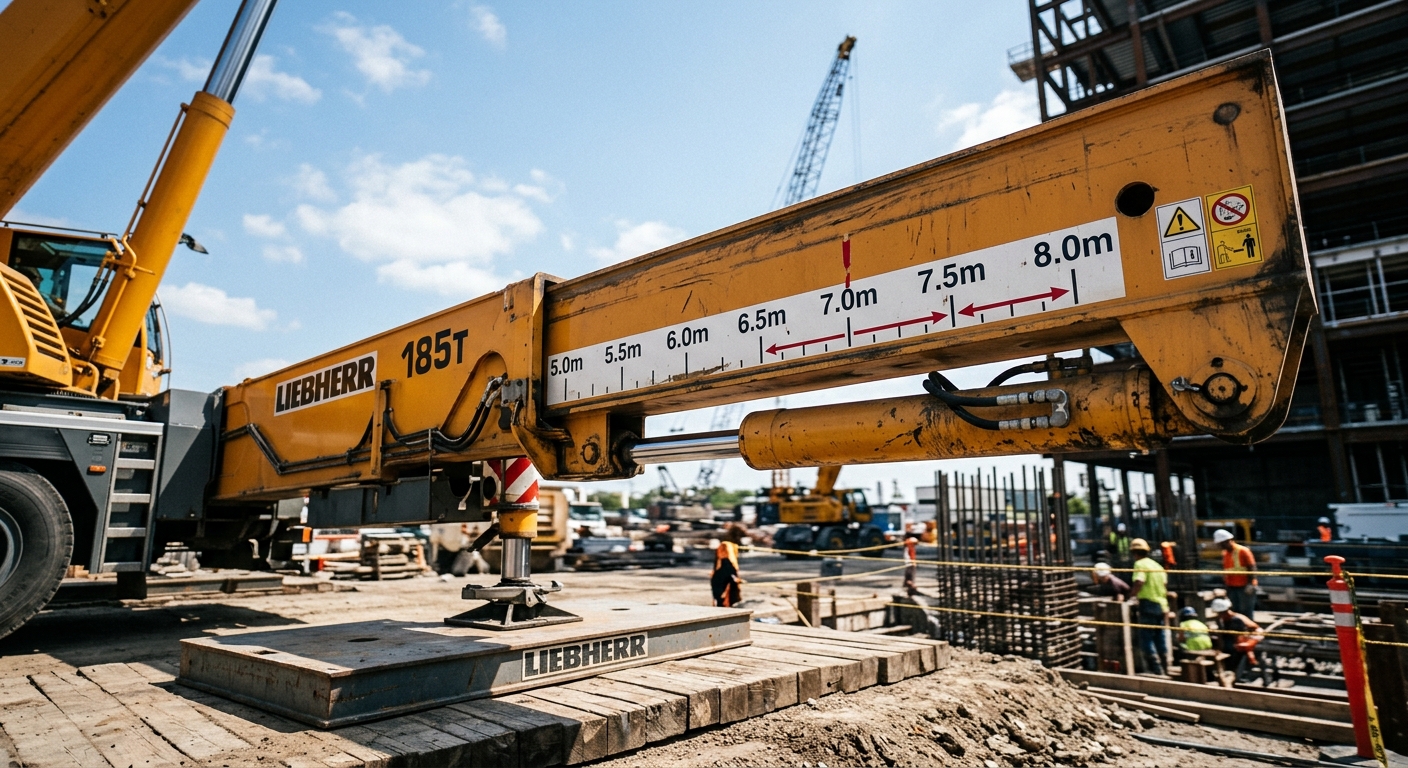
Most operators know outriggers need to go out — fewer understand that the extension position isn’t a preference, it’s a completely different load chart. A crane rated for 55 tons at full outrigger extension might only handle 15-18 tons at minimum extension. That’s not a small derate. It’s a different machine, capacity-wise.
Rough terrain and truck cranes typically offer 3-4 extension positions: full, 3/4, mid, and minimum (or “stowed”). Each has its own chart page, and the crane’s onboard system usually detects position via sensors and locks out the wrong chart automatically. But on older units or in the field with worn sensors, operators sometimes assume full capacity applies regardless of extension — that assumption has caused more tip-overs than any mechanical failure.
For teams running rough terrain mobile cranes on tight urban or industrial sites, minimum extension is often forced by space constraints. That’s fine — as long as you’re pulling numbers from the correct chart page, not the one you wish applied.

Ground Bearing Pressure: The Number Most Crews Skip Entirely
An outrigger pad can transmit ground pressure north of 40-50 tons per square meter on a fully loaded lift — enough to punch through unreinforced asphalt or soft backfill without warning. This is the single most overlooked step in outrigger setup: nobody calculates it, they just eyeball the ground and hope.
Calculating What the Pad Actually Needs
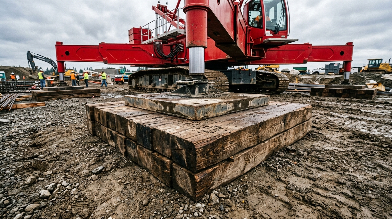
The rule of thumb: outrigger load (from the load chart) divided by pad contact area gives ground bearing pressure, which then gets compared against the soil’s bearing capacity. Compacted gravel might handle 15-20 tons/m², soft clay or fill can drop below 5 tons/m². If the math doesn’t work, you add cribbing — timber mats, steel plates, or engineered outrigger pads — to spread the load over a wider area.
A Real Setup Scenario
For instance, a crane rental company setting up a 30-ton lift near a recently backfilled trench found their standard 600mm x 600mm pads would have generated pressure well beyond what the disturbed soil could bear. They switched to 1.2m x 1.2m timber mats under each pad, which dropped the bearing pressure to a safe margin — a five-minute fix that avoided a very expensive sink. This is exactly the kind of detail worth confirming before mobilizing equipment like a 30 ton rough terrain crane onto unfamiliar ground.

Leveling Tolerance: Why 1 Degree Off Matters More Than You Think
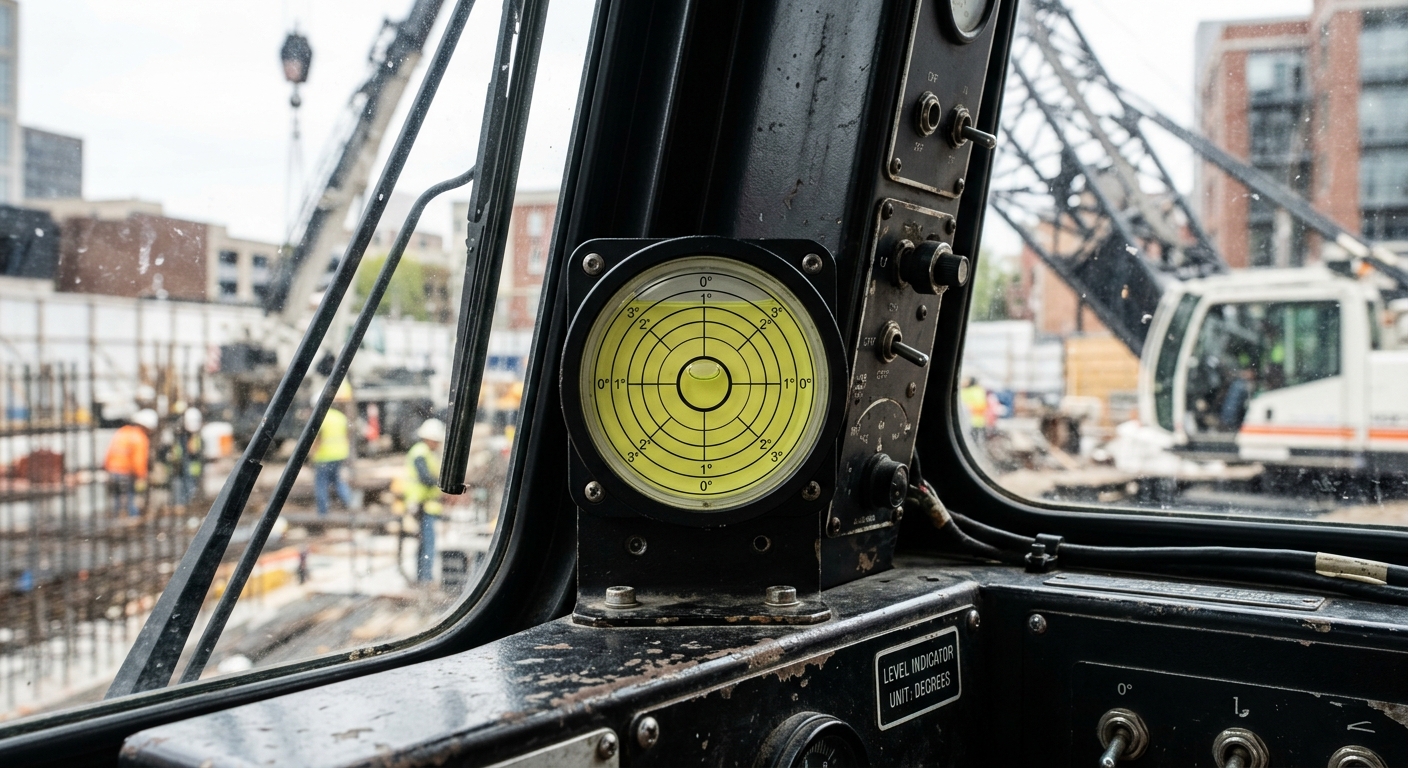
Most cranes require leveling within 1 degree — some manufacturers specify tighter, around 0.5 degrees — measured by a bubble level or electronic inclinometer built into the carrier. That sounds trivial until you realize a 1-degree tilt on a fully extended boom can shift the load’s effective radius by several centimeters, enough to push a marginal lift outside the chart.
Leveling isn’t just about avoiding a wobbly cab either. The entire load chart assumes a level machine. Slew the boom over the low side of an unleveled crane and you’ve effectively increased your load radius without the chart accounting for it — capacity that looked fine on paper suddenly isn’t.
The Correct Leveling Sequence
- Set outriggers on stable, checked ground first — leveling before ground verification is backwards.
- Extend and lock all outrigger beams to the required position for the lift.
- Raise outrigger jacks until tires or tracks are fully unloaded (not just touching ground).
- Check the level indicator in two perpendicular directions, adjusting individual jacks as needed.
- Re-check after boom extension and load application — steel settles under weight.

Outrigger Spread: Symmetrical Isn’t Always Possible — Here’s What to Do
Textbook setups show all four outriggers at equal, full extension. Real jobsites rarely cooperate. A wall, a trench, or a neighboring structure can block one beam from reaching full spread while the others go out fine.
Asymmetrical setups are allowed on most modern cranes, but the load chart shifts based on the shortest extended beam, not the average. If three outriggers are at full extension and one is at mid, the crane’s control system (or the operator, on older machines) must apply the mid-extension chart for safety — because that’s the weakest support point in the system.
This is where choosing the right crane tonnage for a constrained site pays off. A crane with margin above the minimum required capacity handles an asymmetrical setup without forcing the crew into a razor-thin safety margin.
Pad Contact and the Problem With Sloped or Uneven Surfaces
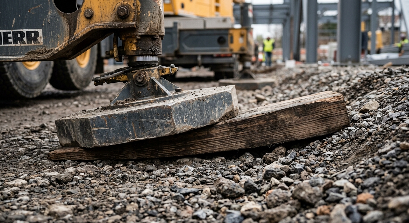
A pad that’s only touching ground on one edge isn’t providing full support — it’s concentrating the entire load onto a fraction of the pad’s surface area, multiplying the effective bearing pressure well beyond the calculated figure. This happens constantly on sloped yards, gravel piles, or poorly graded lay-down areas.
The fix isn’t complicated: pack or shim under the low side until the pad sits flat, or use a wedge-shaped crib block designed for the slope angle. Some crews skip this because it looks close enough — but “close enough” on a pad edge can mean 30-40% of the intended contact area, which defeats the entire ground bearing calculation from earlier in the setup.
Quick Field Check
Slide a straightedge or level bar under the pad edge before loading. If light passes underneath, the pad isn’t fully seated — stop and shim before continuing.

Setup Sequence for Confined Sites: A Practical Walkthrough
Urban and industrial retrofit sites rarely offer the luxury of full outrigger spread. Here’s a realistic sequence a crew might follow when setting up a truck crane in a tight yard between two buildings.
- Step 1: Survey the footprint — measure actual available space against the crane’s mid and minimum extension charts before positioning the carrier.
- Step 2: Confirm ground type and add cribbing preemptively if surface is asphalt over unknown subgrade.
- Step 3: Position carrier so the heaviest anticipated lift direction aligns with the longest available outrigger spread.
- Step 4: Extend outriggers to the maximum position the site allows — never assume minimum extension just because space is tight everywhere else.
- Step 5: Level, then re-verify with a test lift at reduced load before committing to the full rigging plan.
This kind of constrained setup is common with a 12 ton crane truck working infill construction sites, where every meter of outrigger spread has to be negotiated against fences, utilities, and neighboring foundations.
When Outriggers Alone Aren’t Enough: Counterweight and Chart Interaction
Outrigger setup doesn’t work in isolation — it interacts directly with counterweight configuration and boom angle. A crane set up perfectly on outriggers but missing required counterweight will still fail the stability check, because the load chart assumes both variables are correct simultaneously.
This matters most on heavier capacity machines. A 100 ton mobile crane or larger unit often has multiple counterweight configurations tied to specific outrigger extension positions — meaning the chart you pull depends on both settings together, not either one alone. Crews that only double-check outrigger position while assuming counterweight is “close enough” are working off an incomplete picture.